Tuesday, May 02, 2017

What is meant by Bar Bending Schedule (BBS)?

Bar Bending Schedule, commonly referred to as “BBS” is a comprehensive list that describes the location, mark, type, size, length and number, and bending details of each bar or fabric in a Reinforcement Drawing of a Structure.
This process of listing the location, type and size, number of and all other details is called “Scheduling”. In context of Reinforcement bars, it is called bar scheduling. In short, Bar Bending Schedule is a way of organizing rebars for each structural unit, giving detailed reinforcement requirements.
Bar-Bending-Schedule.jpg

General guidelines to be followed in preparing BBS:

  • The bars should be grouped together for each structural unit, e.g. beam, column, etc.
  • In a building structure, the bars should be listed floor by floor.
  • For cutting and bending purposes schedules should be provided as separate A4 sheets and not as part of the detailed reinforcement drawings.
  • The form of bar and fabric schedule and the shapes of bar used should be in accordance with BS 8666.
  • It is preferable that bars should be listed in the schedule in numerical order.
  • It is essential that the bar mark reference on the label attached to a bundle of bars refers uniquely to a particular group or set of bars of defined length, size, shape and type used on the job.
  • This is imperative as a bar mark reference can then point to a class of bar characteristics. Also, this helps steel fixers and laborers keep track of the type and number of bars needed to complete a certain work.

Bar Bending Schedule is used by the:

  • Detailer
  • person checking the drawing
  • contractor who orders the reinforcement
  • organization responsible for fabricating the reinforcement
  • steel fixer
  • clerk of works or other inspector
  • the quantity surveyor
Quantity surveyor is responsible for estimation and costing operations of a project. This kind of surveying demands a high level of precision. Bar Bending Schedule helps the quantity surveyor to consolidate the number of bars required of each bar type.
This leads to an estimation of the quantity of steel, which translates to the cost requirements for steel work.  Hence, BBS is used by the contractor who orders the reinforcements as well. Unit cost of steel is charged by weight of steel purchased.
Clerk of works and other inspectors refer to the BBS to make sure that the reinforcement work in the site is in tandem with the design requirements as per drawings. It is used as a frame of reference by the steel fixers firsthand. They can easily make note of the number and kind of rebar needed for a structural unit.
In essence, Bar Bending Schedule subsumes all necessary information on reinforcements, used by professionals at various stages of the construction process, right from procurement to finish.

How to prepare a BBS?
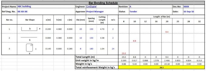
Necessary Columns

  • Bar number/Bar Mark Reference
  • Bar shape
  • Diameter
  • Spacing
  • Length of bar
  • Cutting Length
  • Number of bars
Most of the information in a BBS can be found in reinforcement drawings of the structural unit. Bar shape, diameter, length and spacing is directly entered in the schedule just by looking at the drawings, which will have detailed dimensioning.

What is Beta Angle in Staadpro?

Beta Angle
When the local x-axis is parallel to the global Vertical axis, as in the case of a column in a structure, the beta angle is the angle through which the local z-axis (or local Y for SET Z UP) has been rotated about the local x-axis from a position of being parallel and in the same positive direction of the global Z-axis (global Y axis for SET Z UP).
When the local x-axis is not parallel to the global Vertical axis, the beta angle is the angle through which the local coordinate system has been rotated about the local x-axis from a position of having the local z-axis (or local Y for SET Z UP) parallel to the global X-Z plane (or global X-Y plane for SET Z UP)and the local y-axis (or local z for SET Z UP) in the same positive direction as the global vertical axis. Figure details the positions for beta equals 0 degrees or 90 degrees. When providing member loads in the local member axis, it is helpful to refer to this figure for a quick determination of the local axis system.

Monday, May 01, 2017

What are crack repair techniques?

Crack Repair Techniques:
  1. Sealing with epoxies
  2. Routing and sealing
  3. Stitching
  4. External stressing
  5. Overlays
  6. Grouting
  7. Blanketing
  8. Autogenous healing
Sealing with epoxies :
  • Injection epoxy bonding compounds in high pressure in to cracks
PROCEDURE
Sealing with epoxies

  1. Drill into the cracks
  2. Flush out cracks by injecting water/ other solvents
  3. Dry the surface
  4. Epoxy injection in to holes
  5. Curing of epoxy
  6. Remove surface seal by grinding
Routing and Sealing
Routing and Sealing
Routing and Sealing

  • Simplest, most common, inexpensive method
  • For both fine and larger isolated cracks
  • This method involves enlarging the crack along its exposed face and sealing it with a suitable joint sealant
  • Most used for floors and pavements
  • Side effects-
    • Chemical attack
    • Corrosion of rebar
    • Swelling
Stitching
Stitching
Stitching

Stitching may be used when tensile strength must be reestablished across major cracks.


  • Stitching involves
    • drilling holes on both sides of the crack
    • grouting in U-shaped metal units with short legs called staples or stitching dogs


External Stress
  • The development of cracking is due to the tensile stress, thus can be arrested by suppressing this stress
  • Cracks can be closed by inducing a compression force to over come the tensile stresses
  • The compressive force is applied by
    • Pre- stressing wires or rods
    • Wedging- by opening the cracks and filling with expanding mortar, by jacking and grouting or by actual driving wedges.
Blanketing
  • Blanketing is similar to routing and sealing
  • used on a larger scale and is applicable for sealing active as well as dormant cracks.
  • Following are the types of blanketing joints
    • Type I
    • Type II
    • Type III
    • Type IV
      • Type I
      • The first type of blanket joints use elastic sealants
      • They return to their original shape, when not under an externally induced stress
      • A bond breaker should be used at the bottom of the chase, so that the sealant is free to deform.
      • Type II
      • use sealant materials that are known as mastic sealants
      • their details are similar to that of an elastic sealant, except that the bond breaker is omitted and the sealant is bonded to the bottom as well as to the sides of the chase.
      • Type III
      • It is a mortar plugged joint
      • A recess in the form of a trapezoid to accomodate the mortar plug is made
      • This recess is filled with mortar
      • Type IV
      • A water cripped bar is used
Overlays
  • Used to seal cracks
  • Used when large no of cracks, treating each crack is expensive
  • Active cracks- overlays done with materials which are extensible but not flexible. Eg: Polymeric membrane with top coat of tar
  • Dormant cracks- any type of overlays may be used
Eg: polymer modified Portalnd cement mortar or concrete, or by silica fume concrete
Grouting
  • Similar to epoxy injection
  • Epoxy not used where fire resistance and cold weather
  • Grouting is effective alternative
  • When the crack is straight line- drill out the length of crack- grout it to form a key
  • This method is effective in shopping water leaks.
Autogenous Healing
  • It is the natural process of crack repair that can occur in concrete in the presence of moisture
  • The repair is by a combination of mechanical blocking by particles carried into the crack with the water and the deposition of calcium carbonate from the cementitious material
  • Mechanism
  • Autogenous healing occur by the carbonation of calcium oxide and calcium hydroxide present in the cement by CO2 present in the air and water
The resulting CaCO3 and Ca(OH)2 crystals precipitate accumulate and grow through and out from cracks.


Material constant in Staadpro

The material constants are:
modulus of elasticity (E);
weight density (DEN);
Poisson's ratio (POISS);
co-efficient of thermal expansion (ALPHA),
Composite
Damping Ratio, and
beta angle (BETA) or coordinates for any reference (REF) point.
E value for members must be provided or the analysis will not be performed.
Weight density (DEN) is used only when selfweight of the structure is to be taken into account.
Poisson's ratio (POISS) is used to calculate the shear modulus (commonly known as G) by the formula,
G = 0.5⋅E/(1 + POISS)
If Poisson's ratio is not provided, STAAD will assume a value for this quantity based on the value of E.
Coefficient of thermal expansion (ALPHA) is used to calculate the expansion of the members if temperature loads are applied. The temperature unit for temperature load and ALPHA has to be the same.
Composite damping ratio is used to compute the damping ratio for each mode in a dynamic solution. This is only useful if there are several materials with different damping ratios.

How to define constant for concrete structure in staadpro editor?

If all members are in concrete. Than after defining properties you have to define constants. In editor you can define constant command as given below:
CONSTANT
E CONCRETE ALL
DENSITY CONCRETE ALL
POISSON CONCRETE ALL
BETA 40.37 MEMB 62

Where last line is just example showing 40.37 angle and 62 is member number.