The purpose of gantry Girder is to pick and move heavy machinery components within industrial building.
A girder is commonly used many times in the building of bridges.
Gantry girders are used in workshops/factories for movement of cranes which lifts material and shifts from one location to other.
Overhead travelling cranes are used in factories and workshops to lift heavy materials, equipment's, etc. and to carry them from one place to the other.
The bridge was inaugurated on 4th November 2018. Signature Bridge is an elaborated cantilever span cable- stayed bridge, comprising of an asymmetrical inclined namaste-shaped Steel Pylon of 154 m height.
Total length of cable stayed bridge from expansion joint to expansion joint is 575 meters, with main cable- stayed span of 251 meters supported with 15 sets of cables on one side and counterbalanced by 8 back stay cables attached at a rocker bearing on axis 23.
The bridge's steel and concrete composite deck has dual carriageway of 4 lanes, 14 m each, with about 1.2 m central verge, space for anchoring cables, maintenance walkway and crash barrier on either side of the central verge. The outer to outer width of bridge is around 35.20 m and the approach span are about 36 m long. Spherical bearings are provided on all the piers. Pendulum bearing are provided for back stay.
The Steel Pylon of around 154 meters from top of the bearings consists of two legs made up of steel boxes, which merge into one upper pylon body zone made up of a load bearing skin stiffened by internal stiffeners and bracing s, where the cable supporting the main span and the back stays are anchored. Each of the pylon legs consists of a hollow steel box, which would be roughly 50 - 80 meter high. The upper end is the kink diaphragm, which is the transition from pylon leg to the pylon body.
It also has a pylon head, made up of beams and columns in steel structure with a glass cladding. Major part of the steel for pylon is of grade S355. In very highly stressed anchorage zones, S460 grade steel is also used. Each leg of pylon rests on spherical bearings to transmit vertical loads of around 17,000 T.
The deck spans 32 m in transverse direction for B lanes of traffic,4 lanes in each direction. The composite deck consists of two main girders (I- shaped) in longitudinal direction and cross girders at 4.5 m spacing along the deck. Spans are of 13.5 m long on the cable- supported part, 36 m on the approach spans, which are supported over concrete columns. Most part of the deck slab is made up of full depth prefabricated concrete elements of varying thickness from 250 to 350 mm, stitched in- situ over steel girder flanges. In highly stressed areas, near pylon base and backstay anchorage, in-situ concrete up to 700 mm thick is used.
The cables are made up of bundles of parallel 15.7 mm strands of class 1.770 MPa, protected against corrosion with hot dip galvanization & outer PE- pipes. Depending on the location the number of strands per cable varies from 55 to 123 nos. at the main span and is 127 nos. for each backstay.
Under the axis A and C, independent foundations are provided up to the depth of 20 m below ground level as generally rocky stratum was geotechnically determined at that level.
There are 6 numbers of open foundation resting on rocky strata at a depth of about 20m. As the open foundation were to be rested on rock by about 20 m below the ground level, sheet - piled cofferdam was used for excavation by Elevated Lateral Support System (ELS).
All well foundation were required to be done adopting jack down method of sinking for controlling the sinking operation without tilt and shift.
Bogibeel bridge is a combined road and rail bridge over the Brahmaputra river in the north eastern Indian state of Assam between Dhemaji district and Dibrugarh district, which was started in the year 2002 and took a total of 200 months to complete, heavy rainfall in the region being the main cause for the slow progress. Bogibeel river bridge is the longest rail-cum-road bridge in India measuring 4.94 kilometres over the Brahmaputra river. As it is situated in an earthquake-prone area it is India's first bridge to have fully welded steel-concrete support beams that can withstand earthquakes of magnitudes up to 7 on the Richter Scale.
Bogibeel bridge
This is also Asia’s 2nd longest rail-cum-road bridge and has a serviceable period of around 120 years. This is the 5th longest bridge in India after Bhupen Hazarika Setu, Dibang River Bridge, Mahatma Gandhi Setu and Bandra-Worli Sea Link. The bridge was constructed by a consortium of construction companies headed by Hindustan Construction Company. It was inaugurated by prime minister Narendra Modi on 25th December 2018 on the occasion of Good Governance Day.
The Bogibeel bridge traces its origins to the Assam Accord of 1985 and was one of several major infrastructural projects to be set up in Assam in accordance with the pact. It was sanctioned by the Government of India in 1997-98 and was expected to be completed by the end of the Ninth Five Year Plan. The foundation of the bridge was laid in January 1997 by Prime Minister H.D.Deva Gowda, but its construction was inaugurated only in 2002 by Prime Minister, A.B. Vajpayee. The project was to be completed in six years following the inauguration, however the work did not begin until 2007, owing to lack of funds and attention. Consequently, that same year, the Bogibeel bridge was granted a national project status by the Government of India in 2007 by Prime Minister Manmohan Singh, but the implementation was slow, notwithstanding a Congress government in Assam. The Union Ministry of Finance funded 75% of the project costs while the Ministry of Railways financed the rest. The actual work on the project only began in 2011.
The design of Bogibeel bridge has 39 spans of 125 m and a superstructure of composite welded steel truss and reinforced concrete. It is designed to carry a double line 1,676 mm (5 ft 6 in) broad gauge railway on the lower deck and a 2-lane road on the upper deck. With its proximity to the China border, the bridge also has tremendous significance for India's defence and has been built strong enough to support the movement of tanks and even fighter jet landings. It is the longest combined rail and road bridge in India and second longest bridge in Assam over the river Brahmaputra after Bhupen Hazarika Setu which is a road bridge of length 9.15 km.
#Bogibeel, The #longest #Rail- Cum - #Road #Bridge in #India
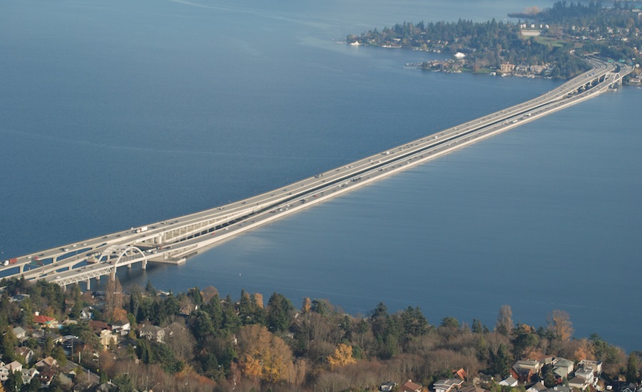
Lacey V. Murrow Memorial Bridge, Seattle, U.S.A, 2,020 meters, 1940. The bridge carries the eastbound lanes of Interstate 90 across Lake Washington from Seattle to Mercer Island, Wash. The world’s first floating bridge to be built using concrete pontoons, it was designed by engineer Homer Hadley, and constructed by the Puget Sound Bridge and Dredging Co., at a price tag of $9 million. While undergoing reconstruction in 1990, an 850-m-long section of the bridge sank when a storm filled one pontoon. The rebuilt bridge reopened in 1993, at a cost of $93 million
Pile integrity test (PIT) is low strain impact integrity test, is a common non-destructive test method for the
-Evaluation of pile cross-sectional area and length, the pile integrity and continuity, as well as consistency of the pile material.
-Forensic evaluations on existing piles, or quality assurance in the new construction.
The integrity test is applicable to driven concrete piles and cast-in-place piles.
Low strain impact integrity testing provides acceleration or velocity and force (optional) data on slender structural elements. Sonic Echo (SE) and Impulse Response (IR) are employed for the integrity test on deep foundation and piles.
The PIT method works best for column type foundations, such as piles and drilled shafts.
How to Perform PIT?
The pile head surface should be accessible, above water, and clean of loose concrete, soil or other foreign materials resulting from construction. Any type of contamination should be removed (using a grinder) to reach to solid and sound concrete surface. This step is so vital, because then connection between the sensor and concrete should be solid (firm contact). The location of the sensor should be selected away from the edges of the pile. The integrity testing should be performed no sooner than 7 days after casting or after concrete strength achieves at least 3/4 of its design strength, whichever occurs earlier.
A hammer (with or without force measurement unit) is used for impacting pile top; the impact should be applied axially with the pile. Motion transducer should be capable of detecting and recording the reflected echos over the pile top. Acceleration, velocity, or displacement transducers can be used for this purpose. At the minimum, acceleration transducer should have an Analog to Digital Converter with 12 bit resolution; and a Sample Frequency of at least 25 KHz.
The distance between the impact location and the sensor should be no larger than 300 mm. Several impacts are applied to the top of the pile. The reflected echos are then recorded for each individual impact. As an alternative, the average can be determined and used. As mentioned earlier, acceleration transducer can be used for the purpose of this test. In this case, the apparatus shall provide signal conditioning and integrate acceleration to obtain velocity. The apparatus shall balance the velocity signal to zero between impact events.
Underslung Movable Scaffolding Systems
Overhead Movable Scaffolding Systems
Underslung Self-Launching Gantries
Overhead Self-Launching Gantries
Underslung Form Travelers
Overhead Form Travelers
Beam Launchers
Precast Full-Span Systems
When the depth of a box girder bridge exceeds 1/6 or 1/5 of the bridge width, it is recommended to be designed as a single cell box girder bridge. However, if the bridge depth is smaller than 1/6 of the bridge width, then a twin-cell or multiple cell is a better choice. However, even for wider bridges with small depths, the number of cells should be minimized
because there is not much improvement in transverse load distribution when the number of cells of box girder is increased to three or more. For multiple-cell box girders, there are generally two arrangements. The first one is that independent cells are connected by their top flanges only while the other one is that the cells are connected both at the top and bottom flanges. From the structural point of view, it is recommended to adopt the second arrangement. For the case of cells connected by top flanges only, their flanges are heavily stressed in the transverse direction owing to flexure which cannot be effectively distributed across the cross section.
Ref: Mastering Different Fields of Civil Engineering Works (VC-Q-A-Method) by Vincent T. H. CHU.
For a variable depth bridge deck, the depth of continuous multi-span bridge deck is increased in pier supports and this absorbs sagging moments in the mid-span with the consequent increase in hogging moments in pier supports.
Basically, piers constructed monolithically with the bridge deck are advantageous in the following ways:
In this way, it saves the construction cost of bearings by using monolithic construction between bridge deck and piers. Moreover, it is not necessary to spend extra effort to design for drainage details and access for bearing replacement. On the other hand, in maintenance aspect substantial cost and time savings could be obtained by using monolithic construction instead of using bearings as bridge.
Monolithic construction possesses the shortest effective Euler buckling length for piers because they are fixed supports at the interface between bridge deck and piers.
Note: Monolithic construction means that piers are connected to bridge decks without any
joints and bearings.
Ref: Mastering Different Fields of Civil Engineering Works (VC-Q-A-Method) by Vincent T. H. CHU.
To acquire a maximum sagging moment in a span of a continuous beam, the general rule is to load the span under consideration and alternative spans on each side of the span. To account for this rule, let’s consider the following example. For instance, loads are applied to the mid-span of a multiple-span continuous beam. It is noticed that this loads induce positive moments near mid-span in all even spans. Therefore, if all even spans are loaded simultaneously, this will result in the increase of positive moments in all other loaded spans. Similarly, to obtain maximum negative moment at a support, load adjacent spans of the support and then alternative spans on each side.
Movement joints are normally added to bridge structures to accommodate movements due to dimensional changes arising from temperature variation, shrinkage, creep and effect of prestress. However, the provision of excessive movement joints should be avoided in design because movement joints always encounter problems giving rise to trouble in normal operation and this increases the cost of maintenance. Some designers may prefer to add more movement joints to guard against possible occurrence of differential settlements. However, the effect of continuity is disabled by this excessive introduction of movement joints.
From structural point of view, the use of continuous deck enhances the reduction of bridge deck thickness. Moreover, deck continuity allows the potential increase in headroom in the mid-span of bridges by using sucker deck principle.
Some designers may prefer to employ the use of simply supported multiple-span deck to guard against possible occurrence of differential settlements. However, the effect of continuity is undermined by the introduction of movement joints. In essence, the structural reserve provided by a continuous bridge is destroyed by the multiple-span statically determinate structure resulting from the addition of joints. Moreover, the reduction of joints in bridge structures represents substantial cost savings arising from the construction and maintenance costs of movement joints. The reduction of deck thickness helps to cut the cost for both the deck and foundation. In particular, the number of bearings in each piers is substantially reduced when compared with the case of simply supported multiple-span deck.
Ref: A Self Learning Manual – Mastering Different Fields of Civil Engineering Works (VC-Q-A-Method) by Vincent T. H. CHU.
The potential benefits of using the bridge form of precast prestressed beams supporting in-situ concrete top slab are:
(i) For bridges built on top of rivers and carriageway, this bridge form provides the working platform by the precast beams so that erection of falsework is not required.
(ii) This bridge form generally does not require any transverse beams or diaphragms (except at the location of bridge supports), leading to reduction of construction time and cost.
(iii) It creates the potential for simultaneous construction with several spans.
Ref: A Self Learning Manual – Mastering Different Fields of Civil Engineering Works (VC-Q-A-Method) by Vincent T. H. CHU.
Stress corrosion is the crystalline cracking of metals under tensile stresses in the presence of corrosive agents. The conditions for stress corrosion to occur are that the steel is subjected to tensile stresses arising from external loading or internally induced stress (e.g. prestressing). Moreover, the presence of corrosive agents is essential to trigger stress corrosion. One of the main features of stress corrosion is that the material fractures without any damage observed from the outside. Hence, stress corrosion occurs without any obvious warning signs.
This question is taken from book named – A Self Learning Manual – Mastering Different Fields of Civil Engineering Works (VC-Q-A-Method) by Vincent T. H. CHU.
The bridge has been designed with a 105m long central span and two 75m long end-spans, and is the only missing piece of the 8.48 km Transport Nagar – Charbagh ‘priority corridor’ of the 22.878 km north-south line which prevents trial runs from commencing on a 2 km stretch between Mawaiya and Charbagh stations.
Slide- In Bridge Construction (SIBC)-A Stepping Stone To Broader Use of all Accelerated Bridge Construction Methods
On a Slide- In Bridge Construction (SIBC) project, a new bridge is built on temporary supports, usually parallel to an existing bridge. During construction, traffic continues uninterrupted on the existing bridge. When construction is compleded, the road is closed temporarily. The existing structure is demolished or removed. The new bridge is positioned in place,tied into the approaches, and paved, generally within 72 hours.
SIBS offers several advantages:
-All the benefits of other ABC technologies.
-Less traffic disruption.
-Greater safety for motorists and construction workers (due primarily to shortened work- zone durations)
- Greater quality and constructability
-Reduced enviornmental impacts from vehicle and construction equipment emissions.
SIBC can eliminate construction joints associated with phased construction, leading to a more durable deck.