Thursday, August 03, 2017
Monday, June 19, 2017
China Turns On the World’s Largest Floating Solar Farm
Floating on a lake over a collapsed coal mine, the power station in Anhui province can produce 40 megawatts of energy.

Built by the company Sungrow Power Supply, the power plant will produce enough energy to power 15,000 homes, Zheng reports.
Anhui province is a coal-rich region, and the Sungrow plant is located on a lake that was once the site of intensive mining. Heavy rains filled the area with water. As Zhen reports, the depth of the lake varies from 12 feet to 30 feet.
Wednesday, May 03, 2017
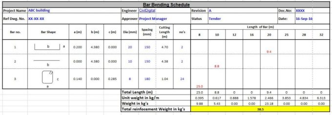
What is meant by Bar Bending Schedule (BBS)?
Bar Bending Schedule, commonly referred to as “BBS” is a comprehensive list that describes the location, mark, type, size, length and number, and bending details of each bar or fabric in a Reinforcement Drawing of a Structure.
This process of listing the location, type and size, number of and all other details is called “Scheduling”. In context of Reinforcement bars, it is called bar scheduling. In short, Bar Bending Schedule is a way of organizing rebars for each structural unit, giving detailed reinforcement requirements.
General guidelines to be followed in preparing BBS:
- The bars should be grouped together for each structural unit, e.g. beam, column, etc.
- In a building structure, the bars should be listed floor by floor.
- For cutting and bending purposes schedules should be provided as separate A4 sheets and not as part of the detailed reinforcement drawings.
- The form of bar and fabric schedule and the shapes of bar used should be in accordance with BS 8666.
- It is preferable that bars should be listed in the schedule in numerical order.
- It is essential that the bar mark reference on the label attached to a bundle of bars refers uniquely to a particular group or set of bars of defined length, size, shape and type used on the job.
- This is imperative as a bar mark reference can then point to a class of bar characteristics. Also, this helps steel fixers and laborers keep track of the type and number of bars needed to complete a certain work.
Bar Bending Schedule is used by the:
- Detailer
- person checking the drawing
- contractor who orders the reinforcement
- organization responsible for fabricating the reinforcement
- steel fixer
- clerk of works or other inspector
- the quantity surveyor
Quantity surveyor is responsible for estimation and costing operations of a project. This kind of surveying demands a high level of precision. Bar Bending Schedule helps the quantity surveyor to consolidate the number of bars required of each bar type.
This leads to an estimation of the quantity of steel, which translates to the cost requirements for steel work. Hence, BBS is used by the contractor who orders the reinforcements as well. Unit cost of steel is charged by weight of steel purchased.
Clerk of works and other inspectors refer to the BBS to make sure that the reinforcement work in the site is in tandem with the design requirements as per drawings. It is used as a frame of reference by the steel fixers firsthand. They can easily make note of the number and kind of rebar needed for a structural unit.
In essence, Bar Bending Schedule subsumes all necessary information on reinforcements, used by professionals at various stages of the construction process, right from procurement to finish.

How to prepare a BBS?
Necessary Columns
- Bar number/Bar Mark Reference
- Bar shape
- Diameter
- Spacing
- Length of bar
- Cutting Length
- Number of bars
Most of the information in a BBS can be found in reinforcement drawings of the structural unit. Bar shape, diameter, length and spacing is directly entered in the schedule just by looking at the drawings, which will have detailed dimensioning.
Tuesday, May 02, 2017
What is Beta Angle in Staadpro?
Beta Angle
When the local x-axis is parallel to the global Vertical axis, as in the case of a column in a structure, the beta angle is the angle through which the local z-axis (or local Y for SET Z UP) has been rotated about the local x-axis from a position of being parallel and in the same positive direction of the global Z-axis (global Y axis for SET Z UP).
When the local x-axis is not parallel to the global Vertical axis, the beta angle is the angle through which the local coordinate system has been rotated about the local x-axis from a position of having the local z-axis (or local Y for SET Z UP) parallel to the global X-Z plane (or global X-Y plane for SET Z UP)and the local y-axis (or local z for SET Z UP) in the same positive direction as the global vertical axis. Figure details the positions for beta equals 0 degrees or 90 degrees. When providing member loads in the local member axis, it is helpful to refer to this figure for a quick determination of the local axis system.

Monday, May 01, 2017
What are crack repair techniques?
Crack Repair Techniques:
- Sealing with epoxies
- Routing and sealing
- Stitching
- External stressing
- Overlays
- Grouting
- Blanketing
- Autogenous healing

Sealing with epoxies :
- Injection epoxy bonding compounds in high pressure in to cracks
PROCEDURE
 |
| Sealing with epoxies |
- Drill into the cracks
- Flush out cracks by injecting water/ other solvents
- Dry the surface
- Epoxy injection in to holes
- Curing of epoxy
- Remove surface seal by grinding
Routing and Sealing
 |
| Routing and Sealing |
- Simplest, most common, inexpensive method
- For both fine and larger isolated cracks
- This method involves enlarging the crack along its exposed face and sealing it with a suitable joint sealant
- Most used for floors and pavements
- Side effects-
- Chemical attack
- Corrosion of rebar
- Swelling
Stitching
 |
| Stitching |
Stitching may be used when tensile strength must be reestablished across major cracks.
- Stitching involves
- drilling holes on both sides of the crack
- grouting in U-shaped metal units with short legs called staples or stitching dogs
External Stress
- The development of cracking is due to the tensile stress, thus can be arrested by suppressing this stress
- Cracks can be closed by inducing a compression force to over come the tensile stresses
- The compressive force is applied by
- Pre- stressing wires or rods
- Wedging- by opening the cracks and filling with expanding mortar, by jacking and grouting or by actual driving wedges.
Blanketing
- Blanketing is similar to routing and sealing
- used on a larger scale and is applicable for sealing active as well as dormant cracks.
- Following are the types of blanketing joints
- Type I
- Type II
- Type III
- Type IV
- Type I
- The first type of blanket joints use elastic sealants
- They return to their original shape, when not under an externally induced stress
- A bond breaker should be used at the bottom of the chase, so that the sealant is free to deform.
- Type II
- use sealant materials that are known as mastic sealants
- their details are similar to that of an elastic sealant, except that the bond breaker is omitted and the sealant is bonded to the bottom as well as to the sides of the chase.
- Type III
- It is a mortar plugged joint
- A recess in the form of a trapezoid to accomodate the mortar plug is made
- This recess is filled with mortar
- Type IV
- A water cripped bar is used
Overlays
- Used to seal cracks
- Used when large no of cracks, treating each crack is expensive
- Active cracks- overlays done with materials which are extensible but not flexible. Eg: Polymeric membrane with top coat of tar
- Dormant cracks- any type of overlays may be used
Eg: polymer modified Portalnd cement mortar or concrete, or by silica fume concrete
Grouting
- Similar to epoxy injection
- Epoxy not used where fire resistance and cold weather
- Grouting is effective alternative
- When the crack is straight line- drill out the length of crack- grout it to form a key
- This method is effective in shopping water leaks.
Autogenous Healing
- It is the natural process of crack repair that can occur in concrete in the presence of moisture
- The repair is by a combination of mechanical blocking by particles carried into the crack with the water and the deposition of calcium carbonate from the cementitious material
- Mechanism
- Autogenous healing occur by the carbonation of calcium oxide and calcium hydroxide present in the cement by CO2 present in the air and water
The resulting CaCO3 and Ca(OH)2 crystals precipitate accumulate and grow through and out from cracks.
Material constant in Staadpro
The material constants are:
modulus of elasticity (E);
weight density (DEN);
Poisson's ratio (POISS);
Poisson's ratio (POISS);
co-efficient of thermal expansion (ALPHA),
Composite
Damping Ratio, and
Damping Ratio, and
beta angle (BETA) or coordinates for any reference (REF) point.
E value for members must be provided or the analysis will not be performed.
Weight density (DEN) is used only when selfweight of the structure is to be taken into account.
Weight density (DEN) is used only when selfweight of the structure is to be taken into account.
Poisson's ratio (POISS) is used to calculate the shear modulus (commonly known as G) by the formula,
G = 0.5⋅E/(1 + POISS)
G = 0.5⋅E/(1 + POISS)
If Poisson's ratio is not provided, STAAD will assume a value for this quantity based on the value of E.
Coefficient of thermal expansion (ALPHA) is used to calculate the expansion of the members if temperature loads are applied. The temperature unit for temperature load and ALPHA has to be the same.
Composite damping ratio is used to compute the damping ratio for each mode in a dynamic solution. This is only useful if there are several materials with different damping ratios.
Composite damping ratio is used to compute the damping ratio for each mode in a dynamic solution. This is only useful if there are several materials with different damping ratios.
How to define constant for concrete structure in staadpro editor?
If all members are in concrete. Than after defining properties you have to define constants. In editor you can define constant command as given below:
CONSTANT
E CONCRETE ALL
DENSITY CONCRETE ALL
POISSON CONCRETE ALL
BETA 40.37 MEMB 62
Where last line is just example showing 40.37 angle and 62 is member number.
Saturday, April 29, 2017
List of Civil Engineering Companies in the world
This list compiles the top civil engineering companies in the world. This list of major civil engineering companies includes the largest and most profitable civil engineering businesses, corporations, and agencies, all of which have had huge impacts on how modern cities and towns function.
What are the biggest civil engineering companies in the world? What are the most successful civil engineering companies? Scroll down for all the civil engineering answers you need.
- AECOM Technology Corporation
- American Bridge Company
- Arcadis NV
- Balfour Beatty
- Bayside Engineering, Inc.
- Bilfinger
- Brookfield Multiplex
- Carillion
- Chemtech
- Chico
- China Harbour Engineering
- Costain Group
- Creighton Manning Engineering
- Davis Langdon
- Enterprise plc
- Fomento de Construcciones y Contratas
- Fuller, Mossbarger, Scott & May Engineers
- Gourlay Brothers
- Halcrow Group
- Harland and Wolff
- HDR, Inc.
- Implenia
- Salini Impregilo
- Interserve
- Jacobs Engineering Group
- KB2 Consulting Civil and Structural Engineers LLP
- Kier Group
- Laing O'Rourke
- Leighton Holdings
- Mesta
- Morgan Est
- Morgan Sindall Group
- Odebrecht
- Parsons Brinckerhoff
- Philippine National Construction Corporation
- Platipus Anchors
- RHL Design Group, Inc.
- Royal BAM Group
- Sacyr Vallehermoso
- Sadbhav Engineering Limited
- Sir William Arrol & Co.
- Strabag
- Takuyo
- Tutor-Saliba Corporation
- United States Army Corps of Engineers
- URS Corporation
- VINCI
- Vollmer Associates LLP
- Waring Brothers
- Wrought Iron Bridge Company
Thursday, April 27, 2017
StaadPro editor command for concrete member property
The following example shows the required input:
UNIT INCH
MEMBER PROPERTY
1 3 TO 7 9 PRISM YD 18. ZD 12. IZ 2916 IY 1296
11 13 PR YD 12.
14 TO 16 PRIS YD 24. ZD 48. YB 18. ZB 12.
17 TO 19 PR YD 24. ZD 18. ZB 12.
MEMBER PROPERTY
1 3 TO 7 9 PRISM YD 18. ZD 12. IZ 2916 IY 1296
11 13 PR YD 12.
14 TO 16 PRIS YD 24. ZD 48. YB 18. ZB 12.
17 TO 19 PR YD 24. ZD 18. ZB 12.
In the above input, the first set of members are rectangular (18 inch depth and 12 inch width) and the second set of members, with only depth and no width provided, will be assumed to be circular with 12 inch diameter. Note that no area (AX) is provided for these members.
The third and the fourth set of members in the above example represent a Tshape and a TRAPEZOIDAL shape respectively. Depending on the properties (YD, ZD, YB, ZB, etc.) provided, the program will determine whether the section is rectangular, trapezoidal or T-shaped and the BEAM design will be done accordingly.
How do i define Prismatic Properties in Staad?
The following prismatic properties are required for analysis:
- AX = Cross sectional area
- IX = Torsional constant
- IY = Moment of inertia about y-axis.
- IZ = Moment of inertia about z-axis.
In addition, the user may choose to specify the following properties:
- AY = Effective shear area for shear force parallel to local y-axis.
- AZ = Effective shear area for shear force parallel to local z-axis.
- YD = Depth of section parallel to local y-axis.
- ZD = Depth of section parallel to local z-axis.
For T-beams, YD, ZD, YB & ZB must be specified. These terms, which are shown
in the next figure are:
in the next figure are:
- YD = Total depth of section (top fiber of flange to bottom fiber of web)
- ZD = Width of flange
- YB = Depth of stem
- ZB = Width of stem
 |
| Prismatic property nomenclature for a T and Trapezoidal section |
For Trapezoidal beams, YD, ZD & ZB must be specified. These terms, which too
are shown in the next figure are:
are shown in the next figure are:
- YD = Total depth of section
- ZD = Width of section at top fiber
- ZB = Width of section at bottom fiber
Top & bottom are defined as positive side of the local Z axis, and negative side of
the local Z axis respectively.
the local Z axis respectively.
STAAD automatically considers the additional deflection of members due to pure
shear (in addition to deflection due to ordinary bending theory). To ignore the
shear deflection, enter a SET SHEAR command before the joint coordinates. This
will bring results close to textbook results.
The depths in the two major directions (YD and ZD) are used in the program to
calculate the section moduli. These are needed only to calculate member stresses
or to perform concrete design. You can omit the YD & ZD values if stresses or
design of these members are of no interest.
To define a concrete member,you must not provide AX, but instead, provide YD
and ZD for a rectangular section and just YD for a circular section. If no moment
of inertia or shear areas are provided, the program will automatically calculate
these from YD and ZD.
and ZD for a rectangular section and just YD for a circular section. If no moment
of inertia or shear areas are provided, the program will automatically calculate
these from YD and ZD.
 |
| Required Section Properties |
Table is offered to assist the user in specifying the necessary section values. It
lists, by structural type, the required section properties for any analysis. For the
PLANE or FLOOR type analyses, the choice of the required moment of inertia
depends upon the beta angle. If BETA equals zero, the required property is IZ.
lists, by structural type, the required section properties for any analysis. For the
PLANE or FLOOR type analyses, the choice of the required moment of inertia
depends upon the beta angle. If BETA equals zero, the required property is IZ.
Wednesday, April 26, 2017
How do I change a cover to a reinforcement for beams and columns in STAAD.Pro V8i?
Got to Commands- Concrete Design- Design parameters-Clear
 |
| Cover to reinforcement |
Wednesday, April 05, 2017
Core Cutting In Reinforced Cement Concrete Structures
Cores are generally cut with the use of a rotary cutting tool having diamond bits. In this way, a cylindrical specimen is acquired normally with its ends to be unequal, parallel and square and occasionally with embedded pieces of reinforcement.
Core cutting is performed for the following reasons :-
- To detect firmness and density of concrete
- To find out depth of carbonation of concrete
- Chemical analysis
- Water/gas conformity
- Petrographic analysis
- ASHTO Chloride permeability test
Bent Tower for NYC: World’s Longest Skyscraper
New York City’s obsession with building ultra-tall, skinny skyscrapers should come as a surprise to no one. For decades, architects and developers have worked to “out-phallic” each other to seize prestige and obscene amounts of cash. New York-based Oiio Studio has had enough of the taller-is-better trend – and they’re now aiming to create the “longest skyscraper in the world” – aptly dubbed “The Big Bend” – to draw attention to the city’s absurd real estate situation. The proposed Big Bend aims to be the longest skyscraper on the globe – topping out even Dubai’s Burj Khalifa – by folding
the tower in half in an inverted U-shape.
the tower in half in an inverted U-shape.

Big Bend is a 4,000-foot-tall paperclip-shaped skyscraper that would loom over the towers along New York City’s Billionaire’s Row. The plans evoke an ultra-modern atmosphere with images of top-hatted rich men taking center stage in the renderings. According to the architects, the “bendy” design responds to the city’s uber-tall skyscrapers, which have been criticized for “bending” building codes and using their height to command exorbitant prices.
How to Specify member properties graphically in Staadpro?
- To define member properties, click on the Property Page icon located on the top toolbar.

Alternatively, one may go to the General | Property page from the left side of the screen as shown below.


- In either case, the Properties dialog box comes up (see figure below). The property type we wish to create is the W shape from the AISC table. This is available under the Section Database button in the Properties dialog box as shown below. So, let us click on the Section Database button.

For beam and column properties in Rcc structure you have to click on Define button next to Section Database.
- In the Section Profile Tables dialog box that comes up, select W Shape under the American option. Notice that the Material box is checked. Let us keep it that way because it will enable us to subsequently assign the material constants E, Density, Poisson, etc. along with the cross-section since we want to assign the default values.
Choose W12X35 as the beam size, and ST as the section type. Then, click on the Add button as shown in the figure below.

or
For beam and column properties in Rcc structure after clicking on Define button next to Section Database you get dialog box as shown below. Click on Rectangle for rectangular properties.


Saturday, April 01, 2017
How do I change the sizes of reinforcement bars for beams and columns in STAAD.Pro V8i?
Go to Commands - Design - Concrete Design

 |
| Concrete design command |
On right side small window appear, Under current code select your code
 |
| Select code |
Click on Define Parameters- in left panel click on MD1 & MD2

Friday, March 31, 2017
Top 3 Planning and management software of civil engineering
- Microsoft Project
- Primavera
- Project Kickstart
how to check The Dead load as per Staad for no of floors
1. Self weight (columns,beams and shear walls for the entire building)
2. Brickwall over the exterior beams except on shear wall only are added.
3. The dead load on slab- Self weight of slab+Finish+Construction load +15% for furniture, staircase, water tank etc is added with an intensity of 6KN/Sq.m.
2. Brickwall over the exterior beams except on shear wall only are added.
3. The dead load on slab- Self weight of slab+Finish+Construction load +15% for furniture, staircase, water tank etc is added with an intensity of 6KN/Sq.m.
A manual check for these items are carried out as:
- Dead load: Area of floor x no. of floors x intensity of load
- Brickwall load:
Total length of beam in one floor =
Load per floor =
Load due to brickwall alround exterior beams =
Load due to Parapet 1.0 m height of 4.5” wall=
Total dead load due to brickwall = - SELF WEIGHT OF:
- COLUMNS =
- Beams for all floors
- Shear wall:
HOW TO DO MANUAL CHECK AGAINST STAAD RESULTS FOR SEISMIC FORCES?
Example
The structure is 36x21m and is symmetrical in x and Z direction as well as in vertical elevation and its total height from the footing is 74m.(21 storey)
The structure is 36x21m and is symmetrical in x and Z direction as well as in vertical elevation and its total height from the footing is 74m.(21 storey)
The building is in Zone III and the time period as per IS 1893-2002(PartI) for infill is taken 0.09h/√d.
After analysis through STAADPRO the followings check is carried out to verify and check the results between manual calculation and the software results.
-------------------------------------------------------------------------------------------------
-------------------------------------------------------------------------------------------------
A. TIME PERIOD:
As per IS CODE 1893-2002(Part I) T =0.09h/ √d where d is the direction along the EQ forces.
Tx =0.09x74/ √36 =1.11 Sec.
Tz =0.09h/ √21 =1.453 Sec.
Tx =0.09x74/ √36 =1.11 Sec.
Tz =0.09h/ √21 =1.453 Sec.
The output of STAADPRO is
TIME PERIOD FOR X 1893 LOADING = 1.11000 SEC
TIME PERIOD FOR Z 1893 LOADING = 1.45333 SEC
******************************************************************************************
TIME PERIOD FOR Z 1893 LOADING = 1.45333 SEC
******************************************************************************************
Thursday, March 30, 2017
Manual checking of Staadpro output
LOADS:
Correct assessment of loads both dead and live loads are important since excessive assumed loads may lead to uneconomical member sizes and footing sizes. Also excessive loads will be adding more weight in the case of seismic forces.
In order to have equilibrium i.e .ΣV=0 under the Load case DEAD LOAD calculate the total dead load on all floor slabs and check it against the output by the program.
In order to have equilibrium i.e .ΣV=0 under the Load case DEAD LOAD calculate the total dead load on all floor slabs and check it against the output by the program.
METHOD TO CHECK:
Using a single support for the whole structure RUN the ANALYSIS and find out the total support reaction in Y axis i.e FY from the output of the program. Check whether the above two values are in agreement to the manually calculated values. If the results vary then there is some error or mistake took place while entering the input.
The same procedure can be carried out for the LIVE LOAD for both FLOOR LIVE LOAD and ROOF LIVE LOAD cases also.
The same procedure can be carried out for the LIVE LOAD for both FLOOR LIVE LOAD and ROOF LIVE LOAD cases also.
If the single support is not considered or modeled then use all the supports and copy the values of Fy to EXCEL and get the sum of the FY and check whether it tallies with the manually calculated values.
WIND LOAD:
To find the point load FX or FZ at a joint as nodal wind force calculate the tributary area for the corresponding node and multiply it with the intensity of loading.
For example:
Area = (h1+h2)/2*(L1+L2)/2* intensity of loading.
Please note that the consistence unit shall be used.
Where h1 and h2 are the height above and below the joint in meters and L1 and L2 are the width of the bay on either side of the node in meter units.
For example:
Area = (h1+h2)/2*(L1+L2)/2* intensity of loading.
Please note that the consistence unit shall be used.
Where h1 and h2 are the height above and below the joint in meters and L1 and L2 are the width of the bay on either side of the node in meter units.
If h1 =4.0m
and h2=3.0m,
and h2=3.0m,
L1=5.0m
and L2=6.0m
then the tributary area for the node is
=(4+3)/2*(5+6)/2 = 19.25sq.m.
=(4+3)/2*(5+6)/2 = 19.25sq.m.
Using an intensity of 1KN/sq.m the nodal force shall be =19.25 KN.
This can be verified with the values generated by the program.
SUPPORT CONDITIONS:
Usually while modeling a structure either FIXED or HINGED support condition is proposed. If the support condition is FIXED the there shall be six restraints i.s. FX,FY ,FZ, Mx, My and Mz
For HINGED there shall be no moments. In order to account for the soil spring the modulus of subgrade reaction Ks has to be considered for the support condition.
For HINGED there shall be no moments. In order to account for the soil spring the modulus of subgrade reaction Ks has to be considered for the support condition.
Ref: by T.Rangarajan
Manual checking of Staadpro inputs
Model checking
It is important to check the UNITS at every stage while modeling since it may lead to a unexpected error in the output. While modeling use of length units may be in meter for beam, column and plate and while entering the properties it is usual practice to make use of either mms or inch unit . While inputting the LOADS on members check the UNIT system is in KN and meter system since the program continues to use the previous unit till it is changed.
Before inputting the LOADS to the structure facility is available in STAADPRO as per the screen shot.
Check Multiple Structures.
Some times by mistake the user would have without his knowledge created too many members and structure. Better use this tool menu to remove the multiple structures. It is the responsibility of the applicator to verify that there exists only one structure and not more than it for any model.
 |
| Check for multiple structure in Staadpro |
Which type of multiple-cell box girder is better, cells connected by top flanges or cells connected both by top and bottom flanges?
When the depth of a box girder bridge exceeds 1/6 or 1/5 of the bridge width, it is recommended to be designed as a single cell box girder bridge. However, if the bridge depth is smaller than 1/6 of the bridge width, then a twin-cell or multiple cell is a better choice. However, even for wider bridges with small depths, the number of cells should be minimized
because there is not much improvement in transverse load distribution when the number of cells of box girder is increased to three or more. For multiple-cell box girders, there are generally two arrangements. The first one is that independent cells are connected by their top flanges only while the other one is that the cells are connected both at the top and bottom flanges. From the structural point of view, it is recommended to adopt the second arrangement. For the case of cells connected by top flanges only, their flanges are heavily stressed in the transverse direction owing to flexure which cannot be effectively distributed across the cross section.
because there is not much improvement in transverse load distribution when the number of cells of box girder is increased to three or more. For multiple-cell box girders, there are generally two arrangements. The first one is that independent cells are connected by their top flanges only while the other one is that the cells are connected both at the top and bottom flanges. From the structural point of view, it is recommended to adopt the second arrangement. For the case of cells connected by top flanges only, their flanges are heavily stressed in the transverse direction owing to flexure which cannot be effectively distributed across the cross section.

Ref: Mastering Different Fields of Civil Engineering Works (VC-Q-A-Method) by Vincent T. H. CHU.
Wednesday, March 29, 2017
How to see Reinforcement details in Staad.pro?
After you run analysis you can either see in output or postprocessing.
First method
As shown in figure below to see output u have to click on icon
- OUTPUT FILE OF STAADPRO

You will see concrete design option on left click on that
- BEAM REINFORCEMENT RESULT IN STAADPRO

You can see reinforcement on right side.
Second method
or you can see in postprocessing also. Run analysis , go to postprocessing. Than click on beam or column whose reinforcement you want to see. small window will open. Click on concrete design there you can see reinforcement.
- BEAM REINFORCEMENT IN POSTPROCESSING IN STAADPRO

Friday, March 24, 2017
What is sucker deck principle for variable depth bridge decks?
For a variable depth bridge deck, the depth of continuous multi-span bridge deck is increased in pier supports and this absorbs sagging moments in the mid-span with the consequent increase in hogging moments in pier supports.
Thursday, March 23, 2017
Member Incidence command in Staadpro
Example of Member incidence command
1 1 3; 2 3 4; 3 4 2;
Above line indicates member number(1) , starting node (1), and ending node number (3).
member number(2) , starting node (3), and ending node number (4)
member number(3) , starting node (4), and ending node number (2)
separated by single spaces.
What are the advantages of piers constructed monolithically with the bridge deck over usage of bearings?
Basically, piers constructed monolithically with the bridge deck are advantageous in the following ways:
- In this way, it saves the construction cost of bearings by using monolithic construction between bridge deck and piers. Moreover, it is not necessary to spend extra effort to design for drainage details and access for bearing replacement. On the other hand, in maintenance aspect substantial cost and time savings could be obtained by using monolithic construction instead of using bearings as bridge.
- Monolithic construction possesses the shortest effective Euler buckling length for piers because they are fixed supports at the interface between bridge deck and piers.
Note: Monolithic construction means that piers are connected to bridge decks without any
joints and bearings.
joints and bearings.
Ref: Mastering Different Fields of Civil Engineering Works (VC-Q-A-Method) by Vincent T. H. CHU.
Subscribe to:
Posts (Atom)